Petroleum contamination can occur at various types of sites including industrial, commercial, and residential land use settings. Potential PVI issues may be different depending on the unique characteristics (such as nature of release or subsurface lithology) of each site. This appendix summarizes different features that may influence the potential for PVI at some commonly encountered petroleum sites. Nine different types of petroleum sites are used as selected examples in this appendix:
The site type examples detailed in this appendix are examples of common petroleum site types and may not cover all site type possibilities or all site-specific scenarios. Components of the sites described in this appendix may be applicable to other types of petroleum sites. In addition, the site types listed in this appendix are scenarios focused on risk from the potential VI pathway and not on other general indoor air quality issues (such as odors) that may result from indoor sources.
The following site features are discussed for each site type:
The following topics are not addressed in the site descriptions contained in this appendix:
For sites with blended PHC compounds, the fate and transport of blended PHC compounds containing more than 10% ethanol may differ from fuels that contain less than 10% ethanol. Additionally, methane may be generated during the ethanol biodegradation. For more information on this topic, refer to Biofuels: Release Prevention, Environmental Behavior, and Remediation (ITRC 2011).
The following table provides a summary of the characteristics of each type of site discussed in this appendix. Characteristics used to distinguish each type include the presence of specific indicator compounds, the presence of certain carbon-chain ranges, the potential sources of the release, the relative size of the release, preferential pathways potentially associated with the release source, and key assessment factors. Note that the characteristics summarized in the table are characteristics as they relate to the potential for PVI. For example, the indicator compounds listed in the table are compounds that may be important in evaluating the potential for PVI. The group of indicator compounds summarized is not an exhaustive list of possible compounds that may be detected on the particular petroleum site type. Also, note that elevated TPH values may be an indicator that PVI risk is possible and that it may be necessary to conduct further investigation.
|
Characteristic |
Gasoline and diesel USTs |
Commercial and home heating oil tanks |
Refineries |
|---|---|---|---|
|
Common Indicator Compounds |
Gasoline: Diesel: Naphthalene, methane |
Naphthalene, benzene |
|
|
Carbon Chain Range(s) |
C5–C12 Aliphatics C6–C10 Aromatics |
No. 2 Fuel: C8–C21 No. 6 Fuel: C8–C30 |
Various |
|
Potential Release Sources |
USTs, product lines, dispensers, service bays |
USTs, ASTs, product lines |
Underground or aboveground piping, USTs (former and current), ASTs, loading areas, tank pits (current and former), processing units, historical disposal sites |
|
Relative Size |
Small to medium |
Small to medium (pending site of tank release) |
Large |
|
Potential Preferential Pathways |
General utilities, karst/fractured bedrock (location dependent) |
Utilities corridor entering building foundation, sumps in basement, cracks in basement floor, karst/fractured bedrock (location dependent) |
General utilities, pipeline corridors, karst/fractured bedrock (location dependent) |
|
Key Assessment Factors |
Documenting historical and current uses of the site (former UST locations) |
Amount of release, distance to the building foundation |
Documenting historical and current uses of the site. |
|
Characteristic |
Bulk storage facilities |
Pipelines/transportation |
Oil exploration and production sites |
|---|---|---|---|
|
Common Indicator Compounds |
For oil/petroleum/gasoline:: BTEX, naphthalene, methane |
For oil/petroleum/gasoline:, For natural gas: methane, butane, propane, benzene |
|
|
Carbon Chain Range(s) |
Various but most often Diesel: C12–C24 Gasoline: C4–C12 |
Various |
Broad range including crude oil and any number of refined products |
|
Potential Release Sources |
Underground or aboveground piping, ASTs, oil/water separators, loading areas |
Pipeline, pipe joints, valves, flanges, weld points |
Wells and well area, pipelines, gathering lines, mud pits, USTs (and associated piping), ASTs (and associated piping), maintenance facilities, oil water separators |
|
Relative Size |
Variable |
Variable |
Large (many acres/hectares), although smaller parts may be carved out for redevelopment
|
|
Potential Preferential Pathways |
General utilities, pipeline corridors, karst/fractured bedrock (location dependent) |
Gravel bed fill, shallow coarser-grained soil, karst/fractured bedrock (location dependent) |
Natural oil seeps, incorrectly abandoned wells, faults/structures along which VOCs could migrate, karst/fractured bedrock (location dependent) |
|
Key Assessment Factors |
Documenting historical and current uses of the site |
Knowing precisely where the pipeline corridor is |
Documenting historical and current location of all exploration wells and infrastructure on site and site use |
|
Characteristic |
Former manufactured gas plants |
Creosote (wood-treating) facilities |
Dry cleaners using petroleum solvents |
|---|---|---|---|
|
Common Indicator Compounds |
|
Naphthalene, alkyl-naphthalene derivatives, benzene |
|
|
Carbon Chain Range(s) |
C6–C10 aromatics C10–C36 polyaromatics |
C6–26 |
C7–C12, C11–C13 |
|
Potential Release Sources |
Tar holders, oil/water separators, gas holder foundations, purifying boxes, tar wells |
Drip pads, product storage areas, unlined pits, lagoons |
Outside building (especially windows and doors), storage areas, dry wells, drains |
|
Relative Size |
Usually small (min 0.2 acres/0.08 hectares, median 2 acres/0.8 hectares, average 6 acres/2.4 hectares), however some can be larger (max 75 acres/30 hectares)
|
Medium to large |
Small; commonly located in strip malls, but can be stand-alone buildings of less than 0.5 acre (0.2 hectares) |
|
Potential Preferential Pathways |
Permeable zones such as gravel layers, storm and sanitary sewers leading off site, karst/fractured bedrock (location dependent) |
General utilities, karst/fractured bedrock (location dependent) |
Subsurface: utility corridors, improperly abandoned monitoring wells and karst/fractured bedrock features Building structure: cracks in floors/walls, utility conduit entrances, floor drains and associated piping, karst/fractured bedrock (location dependent) |
|
Key Assessment Factors |
Documenting historical and current uses of the site; source areas including gasholders, retort houses, tar wells, oil/water separators, purifying boxes |
Documenting historical and current uses of the site; location of pits |
Documenting historical and current uses of the site. Past solvent use |
At small-scale facilities, such as gasoline stations, petroleum products are typically stored in USTs. According to information obtained from the USEPA OUST, approximately 587,000 USTs nationwide store petroleum or hazardous substances. Of the 501,000 releases reported since the beginning of the program, more than 413,000 of these releases have been addressed (approximately 82%), leaving a backlog of almost 88,000 releases remaining to be cleaned up (USEPA 2012i).
BTEX and naphthalene are the main indicator compounds that may be of concern for PVI from a petroleum UST release. MTBE, ethanol and other alcohols, fuel oxygenates, and to a lesser extent, certain PAHs are also components associated with releases at USTs. The alcohols and oxygenates, however, typically have high aqueous solubilities and low Henry’s law constants, which greatly reduce their potential for PVI.
Potential receptors at this type of site may include those present at the filling station, as well as surrounding residential, commercial, and industrial properties. Potential redevelopment of a site for a different use may change the receptors and should be evaluated.
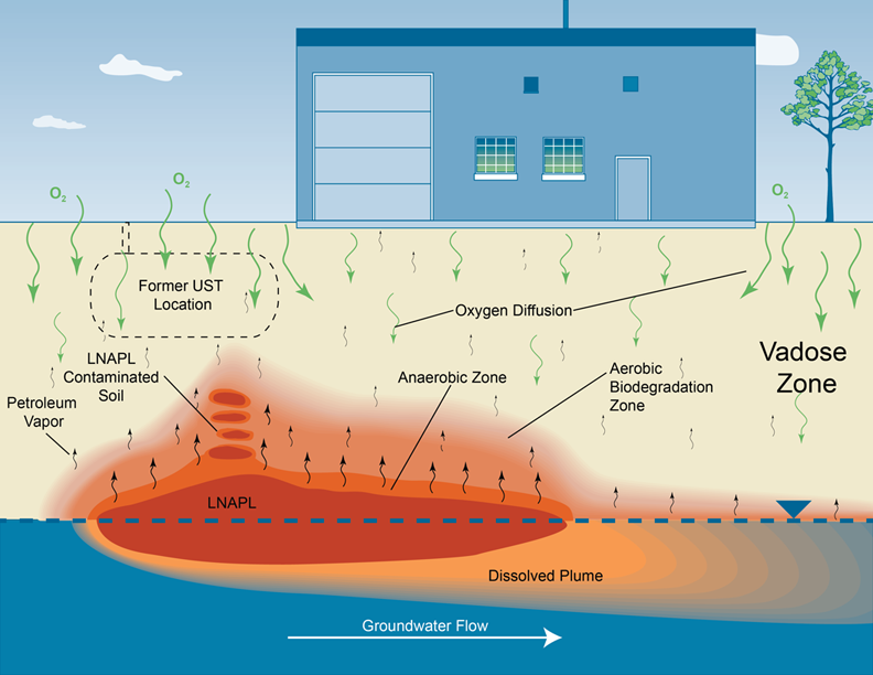
USTs may be constructed of steel, which can corrode over time and allow the contents of the tank to leak into the environment. UST releases may happen suddenly (such as a UST/piping rupture) or gradually (such as a UST/piping perforation caused by corrosion). The size of a UST release depends on the capacity and content of the UST, as well as the rate and duration of the release. Petroleum products released from the UST system enter into the subsurface and may migrate down through the vadose zone to the water table. Depending on the size of the release, the product may pool as LNAPL at the water table and may also dissolve into groundwater and migrate off site as a contaminant plume.
Vapors are released from the free-phase LNAPL and contaminated groundwater. Vapor migration may also occur through natural and artificial pathways present in the subsurface, including UST piping corridors to buildings. Contaminated groundwater may migrate into a basement, basement sump, or foundation drain and release PHC vapors into indoor air. If sources of gasoline and diesel vapors are present near a receptor, the potential for PVI is increased. Figure E-1 depicts a typical site with a UST release as it pertains to the potential for PVI.
Figure E‑1. Petroleum release at a gasoline or diesel UST site.
Additional resources for the evaluation of releases from USTs include guidance documents from IDEM (2012).
Heating oil is commonly used to heat both residential and commercial buildings in many parts of the United States. Releases from commercial and home heating oil tanks are typically small, but may range in size from less than one acre (approximately 0.4 hectares) to several acres (hectares) of land. A release from a site that currently uses heating oil will most likely contain No. 2 fuel oil. Sites where a historical release is suspected, however, will likely contain No.6 fuel oil, which is a heavier fuel oil.
Heating oil can be stored in either ASTs or USTs located inside or outside of the building. The capacity of these tanks can typically range from 250 gallons (946 liters) to 2,500 gallons (9,463 liters) although some tanks may be larger. Releases may be caused by tank corrosion, filter breakage, leakage from the copper line between the tank and furnace, and tank overfills.
Releases from ASTs located on concrete floors in building basements may be more contained within the basement and present a lower potential for PVI (although the release may migrate through the concrete and affect soil and groundwater, which may lead to the potential for PVI). Note that releases from ASTs that are completely contained within the basement may present an indoor air quality issue and are not covered as part of this guidance. Releases from interior ASTs located on dirt floor basements or basement floors with cracks, as well as releases from exterior ASTs located close to the building structure, may contaminate the groundwater and soil beneath the building, leading to the potential for PVI.
Releases from exterior USTs can have potential for PVI if the UST is located near the building or if the volume of the release is enough to contaminate shallow groundwater beneath the building (see Figure E-2). Vapors originating from a leaking heating oil UST or AST may also enter the building through preferential pathways such as utility conduits, sumps, and drains. BTEX, and to a lesser extent certain PAHs (such as naphthalene), are the primary COCs for PVI from commercial/home heating oil releases. Receptors at residential or commercial fuel oil sites typically include residents of the building structure and workers in commercial or office settings. Potential redevelopment of a site for a different use may change the receptors and may need to be evaluated. Nuisance odors may trigger an investigation to determine whether PHC odors are associated with PVI or an indoor air background source (indoor sources of PHCs are not covered as part of this guidance document).
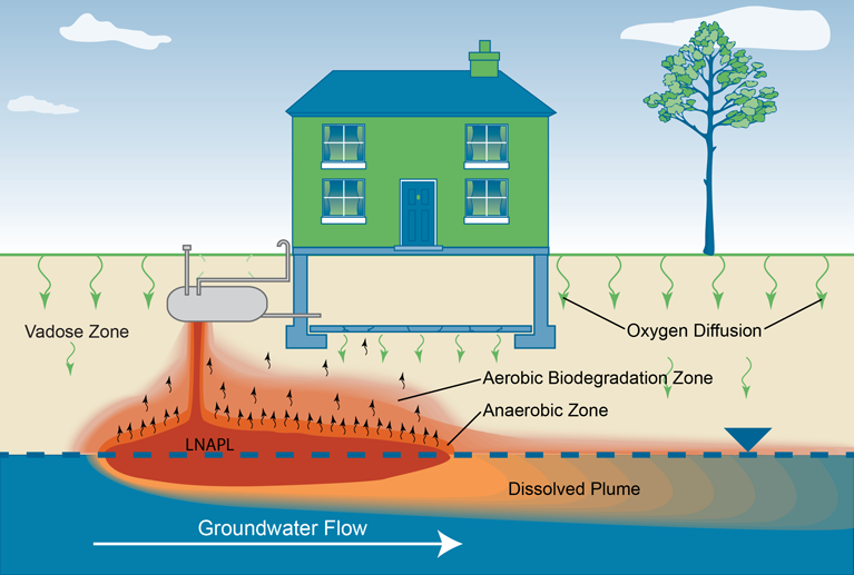
Figure E‑2. Release from a home heating oil tank.
Refineries receive large quantities of unrefined crude oil, which is processed into petroleum products used for fuel and other petroleum-based commercial products (see Figure E-3, Release at a refinery). Refineries are typically large facilities (many acres/hectares) constructed near surface water bodies or large groundwater reserves for use in the process for cooling water, and in the case of navigable surface water bodies, for ease of delivery of crude oil for processing and for shipment of refined petroleum. No new refineries have been built in the United States since 1976.
Conveyance piping at refineries occurs both above and below ground. When releases occur at a refinery, they are typically associated with transfer of the petroleum through the conveyance piping and result from failure of valves or connections, or from corrosion of the infrastructure piping. Refineries use various large storage vessels that contain a variety of refined products and can also be sources of a release. Petroleum or petroleum products within refineries include feedstocks, intermediate process streams, and final products from a variety of sources. Major petroleum or petroleum products (API 2002) that may drive potential PVI risk include:
Large volumes of PHCs are transported and managed at refinery sites, so repeated small spills may create incidental areas with LNAPL-contaminated soils. These LNAPL-contaminated soils can be a source for PHC vapors that is unrelated to LNAPL bodies near the water table. Large pools of LNAPL at the water table are also commonly found at these sites and represent a major source for PVI.
Potential risk drivers at refinery sites are highly variable within a refinery and between refineries as a function of the type of feedstock and end products produced at the refinery. Potential redevelopment of a former refinery site for a different use may require PVI assessment.
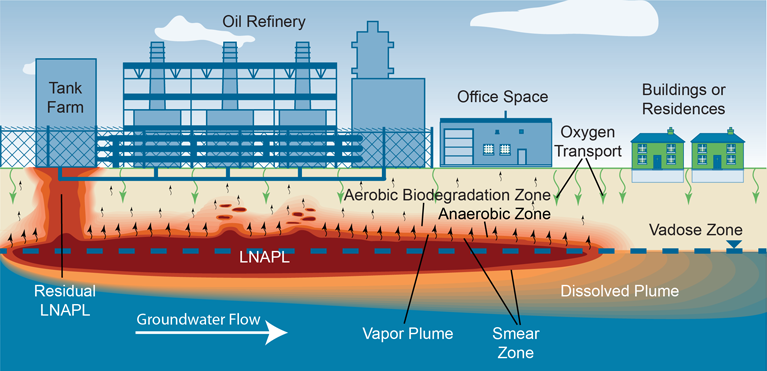
Figure E‑3. Release at a refinery.
A bulk storage facility is one that is used primarily for the storage and transfer of petroleum products. Bulk storage facilities are also referred to as terminals or bulk storage terminals. Bulk storage facilities typically have ASTs with a storage capacity greater than 50,000 barrels (2.2 million gallons/8.3 million liters) and receive petroleum and refined petroleum products by tanker trucks, barges, rail, or pipelines. The types of refined petroleum products transferred at these types of facilities include gasoline, diesel, jet fuel, and heating oil. This transfer is typically through above or underground piping to delivery trucks or rail cars at the loading racks. Figure E-4, Releases at a bulk storage facility, shows typical features at a bulk storage facility.
Petroleum products at bulk storage facilities can be released from surface or subsurface infrastructure. Releases of gasoline (BTEX, naphthalene) present the greatest potential for PVI risk because gasoline contains more volatile components than other petroleum products handled at these sites. Many of the releases are related to the transfer of petroleum from the refinery to the terminal or from the transfer of the stored material to trucks or rail cars. Leaks from the large ASTs are less common than releases associated with the transfer of the petroleum products. Typically, releases from storage tanks will be contained within bermed areas, which act as secondary containment; infiltration from spills will vary depending on subsurface geology and if bermed areas are lined.
The distribution of the released LNAPL depends on the size of the release, location, and the surface and subsurface geology. Surface releases tend to spread following topography. Smaller releases of LNAPL are mainly distributed within the vadose zone; larger releases may migrate to groundwater. Most surface releases are confined to the secondary containment areas at these facilities. Underground releases have the ability to migrate to the water table depending upon the amount of product released and the local geology. Guidance and training on the behavior of LNAPL plumes and their relevance to PVI are available from the ITRC LNAPLs web page (ITRC 2013).
Potential for PVI is minimized when releases are localized and contained within the facility boundaries. The potential for PVI at these sites may be a concern if LNAPL is near an office building or if the property is later redeveloped into another use.

Figure E‑4. Releases at a bulk storage facility.
Pipelines constitute a highly specialized transportation system for the movement of crude oil, refined petroleum products, and natural gas. Crude oil, gasoline, jet fuel and many other petroleum products are transported across continents by large distribution networks of underground pipelines (pipelines are usually placed underground to protect them from damage). New pipelines are being built to meet global demand for oil and gas (Hopkin 2007).
Leaks from subsurface pipelines may not be noticed until the product spreads to the surface, so large releases can potentially contaminate deeper soils and groundwater aquifers before the leak is discovered. Pools of dark liquid on the ground surface near the pipeline, discolored or dead vegetation in the area near a pipeline, and PHC odors are some of the indicators of subsurface pipeline leak. Sizes of pipeline spills depend on the length and size of the piping network and duration of the leak or spill. Depending on the size of the pipelines, the volume of product released in a subsurface spill can be substantial.
Leaks are generally the result of corrosion or cracks in the pipeline; leaks may also occur in the flanges, valves, and other accessories of the pipeline. Knowing the location of the pipeline corridor is a key assessment factor for evaluating pipeline leak sites and establishing the nature of a release is an important part of the site characterization process. Age of the pipeline, dimensions, history and products carried in the line, as well as the history of prior leaks or repairs should also be considered. The typical spill migration path for constituents such as LNAPLs is likely linear (along the length of the pipeline) and downward (under the force of gravity). Depending on the properties of contaminants and the subsurface geology, sufficiently large spills can migrate from vadose zone soil layers to the groundwater table.
The
Utility corridors for pipelines carrying liquid fuel are typically backfilled with coarse material, such as gravel. These permeable fill materials can act as a preferential pathway, aiding in the movement of vapors laterally and upward to the ground surface. PHCs, however, biodegrade relatively well in vadose zone soils when O2 is present. PVI is most commonly associated with free product or high concentrations of dissolved phase TPH in groundwater near a building foundation (NJDEP 2013a). Buildings that are situated very near or over a leaking pipeline should be investigated for PVI if these conditions are identified. Potential redevelopment of a former pipeline corridor for a different use may require PVI assessment. Figure E-5 illustrates the potential for PVI at pipeline sites.
![]()
Figure E‑5. Release from a pipeline.
Oil exploration in the United States has continued for over 150 years. Oil exploration began with settlers and Native Americans finding and using natural oil seeps, and progressed to the large-scale commercial oil drilling and exploration of today.
Oil exploration and production (E&P) sites tend to be relatively large and consist of multiple exploration wells as well as staging, collection, and distribution areas. Parts of an E&P site will operate like the bulk storage facility described in Appendix E.4. Petroleum products at E&P sites range from crude oil to a variety of refined products.
The primary risk drivers are
Natural oil seeps are commonly associated with shallow oil fields, especially those in seismically active areas such as California. Many of the older oil fields were discovered because of oil seeps, and natural oil seeps should be evaluated and documented at E&P sites. Seeps follow a pathway from a subsurface oil source to the surface and may contain higher levels of PHC vapors. The presence of seeps should be evaluated by searching available records regarding discovery and exploration at the site and by visual inspection of the site for localized or isolated oil pools. Because natural oil seeps are pressure driven, it is not possible to eliminate this source. It may be possible, however, to control vapors by capture and venting or treatment if necessary.
Pits, sumps, and spills are present at E&P sites and are potential source areas for PVI. Older E&P sites (pre-1990s) may not have lined pits and sumps, and thus present the potential for more widespread leakage from these features. These on-site waste and storage facilities can contain a wide range of compounds dominated by PHCs, but may include chlorinated compounds, as well. A detailed description of the large number of waste materials that can be present in E&P sumps and pits is presented in Wascom's study (2007). Pits, sumps, and spills are easily located through visual inspection of the site. Older or abandoned facilities can be located through evaluation of records of past site use, historical aerial photos, and interviews with former workers. Unlike seeps, sources in sumps and pits can be remediated to reduce or eliminate the potential for PVI.
Exploration and production wells are also present at E&P sites and may provide a potential preferential pathway for the migration of PHC vapors. The potential for PVI by these preferential pathways may be greater in older fields, as shown in Figure E-6, where completion methods were not designed to eliminate leakage of reservoir gas to the surface. Many older fields may also contain exploration wells that were abandoned using methods that are not appropriate for eliminating the PVI pathway. Records for the E&P site should be evaluated to locate exploration and production wells that were drilled on the property. Existing wells should be abandoned properly to reduce potential for future leakage. Older wells may need to be evaluated to determine whether they were abandoned properly. It may be necessary to collect soil gas samples around older wells to document whether leakage is currently taking place. Gases that are of particular concern at E&P sites include benzene, the primary risk driver, and methane, the primary safety issue.
Other features that can be present on E&P sites include tanks, transfer pipelines, well pads, maintenance facilities, equipment yards, and roadways. Records, interviews with past workers, and aerial photos can be used to determine whether these features were present and, if so, where they were located. Existing structures may need to be removed to reduce or prevent PVI risk. Potential redevelopment of a former E&P site for a different use may require PVI assessment.

Figure E‑6. Exploration and production site.
A manufactured gas plant (MGP) is an industrial facility where gas was produced from coal, oil, and other feedstocks. MGPs operated from the mid-1800s to around the mi
During operation of the MGP, a dense, oily liquid known as coal tar would condense at several stages during gas production, purification, and distribution. Although most of the tar was collected for sale or reuse, recovery was usually incomplete. Most plants had tar/water separators, which sometimes could not fully separate the two liquids. The resulting tar/water emulsion was commonly discharged to a nearby surface water body. Over decades of plant operation, substantial amounts of tar also leaked from storage and processing facilities and contaminated surface soils, subsurface soils, and groundwater. Leakage from underground tanks and piping could contaminate soil and groundwater. Historical information including Sanborn Fire Insurance maps, old photographs, and site drawings may be used to identify former structures and potential source areas. PHCs can generally be found near the gasholders which were used to store gas prior to distribution, or near underground tar wells, tar holders, oil/water separators, purifying boxes, or under “gas oil” storage tanks (kerosene-like oil used in carbureted water gas plants). MGP sites using the coal carbonization process may have separate gas purification areas apart from the retort house.
PHCs present in soil or groundwater generally consist of volatile
PAHs are typically found near site sources because of their affinity to bind to soil and low solubility in water. Aromatic VOCs may travel farther from sources, as dissolved constituents in the groundwater. Preferential pathways for vapors may include permeable zones such as gravel layers, storm and sanitary sewers leading off site, and karst/fractured bedrock.
Evaluation of the PVI pathway at former MGP sites begins with identification of potential source areas; see Figure E-7, Releases at a former manufactured gas plant. Based on the history of MGP sites, potential receptors may include commercial and industrial workers or residents in homes built over or adjacent to the MGP. Although PHCs may be found in the soil or groundwater at MGP sites, there is a growing body of evidence that the potential for PVI is relatively low at most sites. In one study,
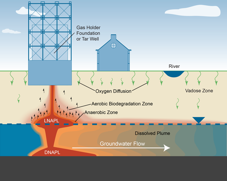
Figure E‑7. Release at a former manufactured gas plant.
Creosote (wood-treating) facilities processed coal tar to produce creosote (and other distillation fractions), then treated wood with the creosote. Historically, creosote was refined from coal tar produced at MGPs, but some sources of creosote were refined from pine tar, a by-product of charcoal production. Coal tar creosote was patented in 1836 by Moll, and John Bethell obtained a patent in 1838 for a pressure impregnation process (Freeman et al. 2003). The first factory began treating railroad ties in 1865, and treated railroad ties have since been used across the country. In 2003 alone, U.S. railroad companies installed an estimated 17 million creosote-treated wood ties according to the American Creosote Council website (American Creosote Council 2013). Creosote is also used to treat utility poles, marine pilings, and other wood products for outdoor use.
Wood treating facilities containing creosote and other chemicals have been the subject of numerous Superfund cleanup efforts. USEPA issued a Presumptive Remedy document in 1995 identifying methods to remediate soil and groundwater (USEPA 1995). Areas of potential concern at wood treatment sites include drip pads, product storage areas, processing areas, unlined pits, unlined surface impoundments, and lagoons. Some wood preserving sites contained both coal tar distillation areas for creosote production, as well as separate wood treatment areas. Creosote sites can range from a few acres/hectares to several hundred acres/hectares with volumes of contaminated soil ranging from tens of thousands of cubic meters to hundreds of thousands of cubic meters. Potential receptors include occupants of buildings built on or adjacent to wood treating facilities. Potential redevelopment of former wood treating facilities may require further PVI assessment.
Coal tar creosote is a complex mixture typically composed of approximately 85% PAHs and 2% to 17% phenolic compounds (ASTDR 2002). The PAHs are generally less volatile and less soluble than VOCs. Coal tars and creosotes are slightly heavier than water and tend to sink when released to groundwater or surface water; see Figure E-8, Releases at a creosote (wood treating) facility. After reaching the water table, the soluble components may partition to the dissolved phase, and the lighter compounds may volatilize. Therefore, COCs at creosote sites are primarily naphthalene and its alkyl derivatives. BTEX compounds may be present in leachate and contaminated water. As creosote ages, the more volatile and soluble compounds of the mixture diminish relative to the less volatile and soluble compounds (USEPA 2014b). Diesel fuel may also be present since it was often used as a solvent for creosote.
A study of PVI from a soil source has been conducted at the former Reilly Superfund site in St. Louis Park, MN. The results indicate that the risk from vapor intrusion is within or below the USEPA’s acceptable risk range. The Five Year Review for the Cabot/Koppers site in Gainesville, FL suggests that the potential for PVI “…can be evaluated prior to the next Five Year Review as the protocols are finalized” (USEPA 2011a). Study results of the potential for PVI from a soil source at creosote wood-treating facilities were not available during preparation of this document; however, the potential for PVI may be relatively low because the by-products are similar to those at former MGP sites (Appendix E.7).
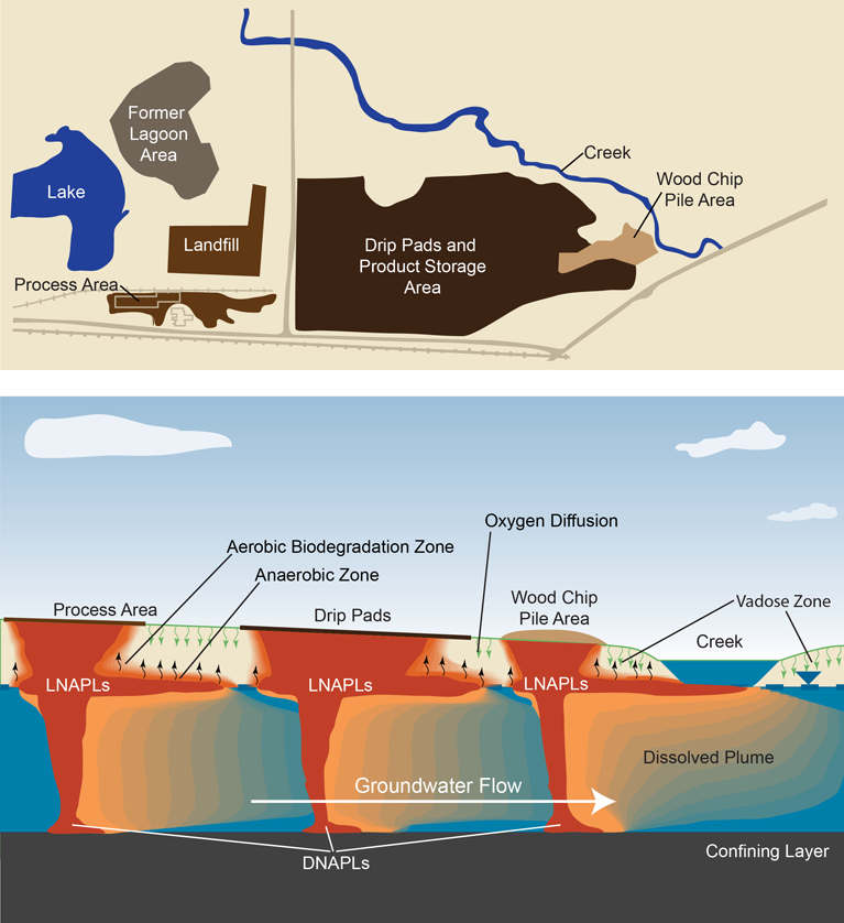
Figure E‑8. Release at a creosote (wood treating) facility.
Historically, the most common petroleum product used in the dry cleaning industry was Stoddard solvent, which is a mixture of aliphatic and alicyclic hydrocarbons in the C7–C12 range. Some currently used, high flash solvents are in the C11–C13 range. Currently, it is estimated that fewer than 15% of dry cleaners in the United States use petroleum solvents. The practice is more prevalent in the southern United States, with estimates of 45% to 50% of dry cleaners using these solvents (SCDHEC 2004).
Dry cleaning facilities are commonly located in strip malls, but can also be stand-alone buildings on small lots typically less than 0.5 acre (0.2 hectares). Off-site migration of contaminants in groundwater or as soil gas plumes poses a potential concern for PVI. Potential receptors may include commercial and industrial workers on site or residents in homes adjacent to the dry cleaning facility. Potential redevelopment of a former dry cleaner site for a different use may require PVI assessment. See Figure E-9, Release of petroleum-based solvents from a dry cleaners.
Preferential pathways for PVI include utility corridors, improperly installed/abandoned/damaged monitoring wells, cracks/holes in floor slabs, basement sumps, and naturally occurring subsurface features such as caves, sinkholes, and fractured bedrock.
Releases to the environment generally occur through improper waste disposal and storage practices. Other sources for a potential release can include spills, container rupture, or faulty equipment. Most spills release less than a few of gallons/liters of product; however, poor housekeeping and improper waste disposal practices may release a significantly greater volume of solvent.
Dry cleaning facilities that use petroleum solvents typically pose a lower risk for VI than facilities that use tetrachloroethene, because petroleum solvents degrade under aerobic conditions. Therefore, an important part of the assessment for the potential for PVI at a dry cleaning facility is to assess which solvents have been used at the facility throughout the operational history. It is not uncommon for a facility to have switched from one type of solvent to another. ITRC provides guidance on assessing the potential for VI at a dry cleaner using CVOCs in Vapor Intrusion Pathway: A Practical Guideline (ITRC 2007)
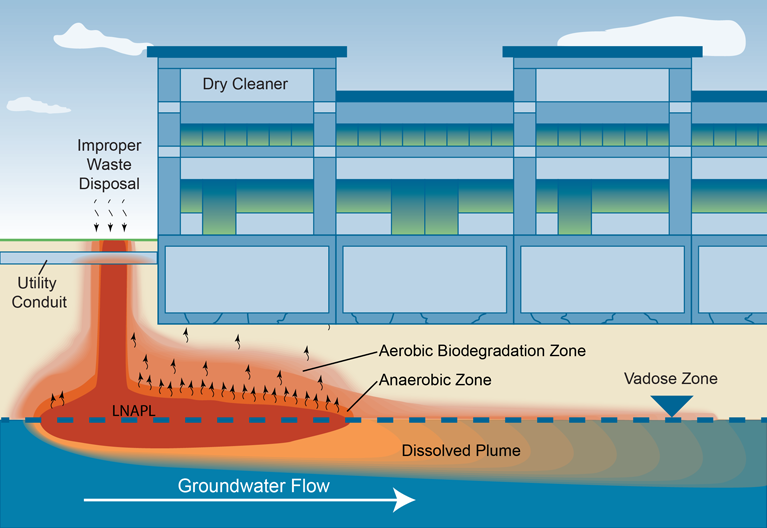
Figure E‑9. Release of petroleum-based solvent from a dry cleaners.